
a special type of orthogonal projection, called iosmetric projection is used in many RTS games
Last UpdaApril 26, 2010Date -->
Once a 3D model has been completed, its co-ordinates need to be converted to 2 dimensions in order to display the scene on a flat computer monitor or to print it on paper. This process of converting from 3D to 2D is called projection. The visual appearance of a 3D model depends on the position of the viewer (among other things), so this must be taken into account when projecting a model. There are two main types of projection available, parallel and perspective.
Parallel projections are used by drafters and engineers to create working drawings of an object which preserves scale and shape. In parallel projection, image points are found at the intersection of the view plane with a ray drawn from the object point and having a fixed direction. The direction of projection is the same for all rays (all rays are parallel). A parallel projection is described by prescribing a direction of projection vector $\vec{v}$ and a viewplane. The object point $P$ is located at $(x,y,z)$ and we need to determine the image point coordinates $P'(x',y',z')$ . If the projection vector $ \vec{v}$ has the same direction as the viewplane normal, then the projection is said to be orthogonal, otherwise the projection is oblique.
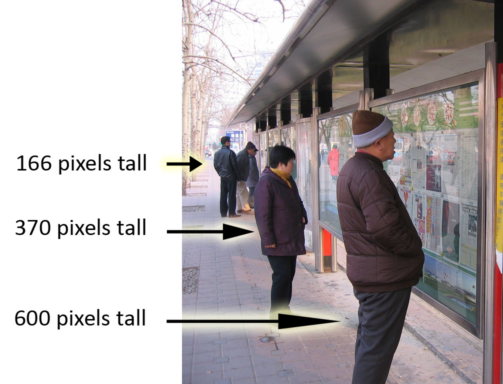
Perspective projections are used to produce images which look natural. When we view scenes in everyday life far away items appear small relative to nearer items. This is called perspective foreshortening. A side effect of perspective foreshortening is that parallel lines appear to converge on a vanishing point. An important feature of perspective projections is that it preserves straight lines, this allows us to project only the end-points of 3D lines and then draw a 2D line between the projected endpoints.
Perspective projection depends on the relative position of the eye and the viewplane. In the usual arrangement the eye lies on the z-axis and the viewplane is the $xy$ plane. To determine the projection of a 3D point connect the point and the eye by a straight line, where the line intersects the viewplane. This intersection point is the projected point.


Perspective projections, while providing a realistic view of an object, are rather restrictive. They require that the eye to lie on a coordinate axis and that the viewplane must coincide with a coordinate plane. If we wish to view an object from a different point of view, we must rotate the model of an object. This causes an awkward mix of modelling (describing the objects to be viewed) and viewing (rendering a picture of the object). We will develop a flexible method for viewing that is completely separate from modling, this method is called the synthetic camera. A synthetic camera is a way to describe a camera (or eye) positioned and oriented in 3D space. The system has three principle ingredients:
The view plane is defined by a point on the plane called the View Reference Point(VRP) and a normal to the viewplane called the View Plane Normal(VPN). These are defined in the world coordinate system. The viewing coordinate system is defined as follows:
In order for a rendering application to achieve the required view, the user would need the specify the following parameters.
To Choose a VPN( $\vec{n}$ ), the user would simply select a point in the area of interest in the scene. The vector $\vec{n}$ is a unit vector, which can be calculated as follows;
The user should select some point in the scene which (s)he would like to appear as the center of the rendered view, call this point $\vec{scene}$ . The vector $ \vec{norm}$ , a vector lying along $\vec{n}$ can then be calculated:
\[\vec{norm}=\vec{scene}-\vec{VRP}\]
$\vec{n}$ must be a unit vector along $\stackrel{\longrightarrow}{\mathbf{norm}}$ ;
\[ \mbox{$\vec{n}$}=\frac{\mbox{$\stackrel{\longrightarrow}{\mathbf{norm}}$}}{|norm|} \]Finally the upward vector must be a unit vector perpendicular to $\vec{n}$ , let the user enter a vector $\stackrel{\longrightarrow}{\mathbf{up}}$ and allow the computer to calculate an appropriate vector $\vec{v}$ .
\[\begin{eqnarray*} \mbox{$\stackrel{\longrightarrow}{\mathbf{up'}}$}&=&\mbox{$\vec{up}$}-k\mbox{$\vec{n}$}\\ \mbox{$\vec{up'}$}.\mbox{$\vec{n}$}&=&0\\ (\mbox{$\vec{up}$}-k\mbox{$\vec{n}$}).\mbox{$\vec{n}$}&=&0\\ \mbox{$\vec{up}$}.\mbox{$\vec{n}$}&=&k\mbox{$\vec{n}$}\mbox{$\vec{n}$}=0\\ \mbox{$\vec{up}$}.\mbox{$\vec{n}$}&=&k|\mbox{$\vec{n}$}|^{2}\\ k&=&\frac{\mbox{$\vec{up}$}.\mbox{$\vec{n}$}}{|\mbox{$\vec{n}$}|^{2}}\\ k&=&\mbox{$\vec{up}$}.\mbox{$\vec{n}$}\\ \mbox{$\vec{up'}$}&=&\mbox{$\vec{up}$}-(\mbox{$\vec{up}$}.\mbox{$\vec{n}$})\mbox{$\vec{n}$}\\ \rm {finally;} \quad \mbox{$\vec{v}$}&=&\frac{\mbox{$\vec{up'}$}}{|\mbox{$\vec{up'}$}|}\\ \end{eqnarray*}\]The vector $\vec{u}$ can now be calulated $\vec{u}=\vec{n}\times \vec{v}$ . With the viewing cordinate system set up, a window in the viewplane can be defined by giving minimum and maximum $u$ and $v$ values. The centre of the window (CW) does not have to be the VRP. The eye can be given any position ($\vec{e}=(e_{u},e_{v},e_{n})$) in the viewing coordinate system. It is usually positioned at some negative value on the n-axis, $\vec{e}=(0,0,-e_{n})$.
The components of the synthetic camera can be changed to provide different views and animation effects;
Below is a Java Applet which demonstrates the effects of the synthetic camera. Modify the camera in the right panel. The left panel shows the view from the eye.
We have developed a method for specifying the location and orientation of the synthetic camera. In order to draw projections of models in this system we need to be able to represent our real-world coordinates in terms of $ \vec{u}\vec{v}\vec{n}$ .
Converting from one coordinate system to another:
\[\begin{eqnarray*} (x,y)&=&\vec{r}+a\vec{u}+b\vec{v}\\ &=&\vec{r}+\left(\begin{array}{ccccc}a&b \end{array} \right)\left(\begin{array}{ccccc}\vec{u}\\\vec{v}\end{array}\right)\\ \textrm{in three dimensions;}\\ (x,y,z)&=&\vec{r}+\left(\begin{array}{ccccc}a&b&c \end{array} \right) \left(\begin{array}{ccccc}\vec{u}\\\vec{v}\\\vec{n}\end{array} \right)\\ \textrm{let} \quad \mathbf{M} &=& \left(\begin{array}{ccccc}\mbox{$\vec{u}$}\\\mbox{$\vec{v}$}\\\mbox{$\vec{n}$}\end{array} \right)= \left(\begin{array}{ccccc} u_{x}&u_{y}&u_{z}\\ v_{x}&v_{y}&v_{z}\\ n_{x}&n_{y}&n_{z} \end{array} \right)\\ \textrm{and subtract $\vec{r}$ from both sides:}\\ (x,y,z)-\vec{r}&=&\left(\begin{array}{ccccc}a&b&c \end{array} \right)\mathbf{M}\\ \textrm{multiply across by $\mathbf{M}^{-1}$}\\ \textrm{and write $(x,y,z)$ as a vector, $\vec{p}$}\\ \left(\begin{array}{ccccc}a&b&c \end{array} \right)&=&(\vec{p}-\vec{r})\mathbf{M}^{-1}\\ \textrm{$\mathbf{M}$ is made up of orthogonal unit vectors; $\mathbf{M}^{-1}=\mathbf{M}^{T}$}\\ \left(\begin{array}{ccccc}a&b&c \end{array} \right)&=&\vec{p}\mathbf{M}^T-\vec{r}\mathbf{M}^T\\ \textrm{expanding $-\vec{r}\mathbf{M}^T$, we get;}\\ -\vec{r}\mathbf{M}^{T}&=&\left(\begin{array}{ccccc}-r_{x}&-r_{y}&-r_{z} \end{array} \right)\left(\begin{array}{ccccc} u_{x}&v_{x}&n_{x}\\ u_{y}&v_{y}&n_{y}\\ u_{z}&v_{z}&n_{z} \end{array} \right)\\ \end{eqnarray*}\]writing the above as a dot product of vectors;
\[ -\mbox{$\vec{r}$}\mbox{${\mathbf{M}}$}^{T}= \left(\begin{array}{ccccc}-\mbox{$\vec{r}$}.\mbox{$\vec{u}$}&-\mbox{$\vec{r}$}.\mbox{$\vec{v}$}&-\mbox{$\vec{r}$}.\mbox{$\vec{n}$} \end{array} \right) \]Combining the the above displacement with the matrix multiplication into a homogeneous matrix, we get;
\[\begin{eqnarray*} \left(\begin{array}{ccccc}a&b&c \end{array} \right)=\mbox{$\vec{p}$}\mbox{${\mathbf{M}}$}^{T}-\mbox{$\vec{r}$}\mbox{${\mathbf{M}}$}^{T}=\mbox{$\vec{p}$}\left(\begin{array}{ccccc} u_{x}&v_{x}&n_{x}&0\\ u_{y}&v_{y}&n_{y}&0\\ u_{z}&v_{z}&n_{z}&0\\ -\mbox{$\vec{r}$}.\mbox{$\vec{u}$}&-\mbox{$\vec{r}$}.\mbox{$\vec{v}$}&-\mbox{$\vec{r}$}.\mbox{$\vec{n}$}&1\end{array} \right) \end{eqnarray*}\]We will refer to the above matrix as$ \mathbf{\hat{A}}_{wv}$ (world to viewing coordinate transformation). We can now write our coordinate transform as:
\[\begin{eqnarray*} \left(\begin{array}{ccccc}a&b&c \end{array} \right)=\vec{p}\mathbf{\hat{A}}_{wv}\\ \end{eqnarray*}\]The above transformation can be reduced to three simpler relations for computation;
\[\begin{eqnarray*} a&=&(\mbox{$\vec{p}$}-\mbox{$\vec{r}$}).\mbox{$\vec{u}$}\\ b&=&(\mbox{$\vec{p}$}-\mbox{$\vec{r}$}).\mbox{$\vec{v}$}\\ c&=&(\mbox{$\vec{p}$}-\mbox{$\vec{r}$}).\mbox{$\vec{n}$} \end{eqnarray*}\]We now have a method for converting world coordinates to viewing coordinates of the synthetic camera. We need to transform all objects from world coordinates to viewing coordinates, this will simplify the later operations of clipping, projection etc. We should have a separate data structure to hold the viewing coordinates of an object. The model itself remains uncorrupted and we can have may different views of the model.
This equation is valid for values of t between 0 and 1. We wish to find the coordinates of the ray as it pierces the viewplane, this occurs when $r_{n}(t)=0$ , the best way to do this is to find what 'time' $t$ the ray strikes the viewplane so;
\[\begin{eqnarray*} r_{n}(t)=e_{n}(1-t')+p_{n}t'=0 \\ e_{n}-e_{n}t'+p_{n}t'=0\\ e_{n}-t'(e_{n}-p_{n})=0\\ e_{n}=t'(e_{n}-p_{n})\\ t'=\frac{e_{n}}{(e_{n}-p_{n})}\\ \textrm{substituting $t'$\ into $r_{u}(t)$\ and $r_{v}(t)$\ we get;}\\ r_{u}(t')=u'=e_{u}(1-t')+p_{u}t'\\ u'=e_{u}\left(1-\frac{e_{n}}{(e_{n}-p_{n})}\right)+p_{u} \frac{e_{n}}{(e_{n}-p_{n})}\\ \textrm{rearranging gives;}\\ u'=\frac{p_{u}e_{n}-e_{u}p_{n}}{(e_{n}-p_{n})}\\ \textrm{similarly for $v'$;}\\ v'=\frac{p_{v}e_{n}-e_{v}p_{n}}{(e_{n}-p_{n})} \end{eqnarray*}\]This gives us coordinates of the point $(u,v,n)$ when projected on to the view plane. If the eye is on the n-axis, which is the usual case, then both $e_{u}$ & $e_{v}$ are zero, thus $u'$ and $v'$ simplify to;
\[ u'=\frac{p_{u}e_{n}}{(e_{n}-p_{n})} \qquad v'=\frac{p_{v}e_{n}}{(e_{n}-p_{n})} \]Note that $u'$ and $v'$ do not depend on t, this means that every point on the ray projects to the same point on the viewplane. Even points behind the eye ($t<0$ ) are projected to the same point on the viewplane. These points will be eliminated later.
When manipulating 3D entities it is useful to have an additional quantity which retains a measure of depth of a point. As our analysis stands we have lost information about the depth of the points because all points are projected onto the viewplane with a depth of zero. We would like to have something which preserves the depth ordering of points, this quantity will be called pseudodepth, and to simplify later calculation we will define it as;
\[ $n'=\frac{p_{n}e_{n}}{(e_{n}-p_{n})} \]An increase in actual depth $p_{n}$ causes an increase in $n$ as required. The simplified equations for $u'$ ,$v'$ and $n'$ can be re- written as follows:
\[\begin{eqnarray*} u'=\frac{p_{u}e_{n}}{(e_{n}-p_{n})}=\frac{p_{u} e_{n}}{e_{n}(1-\frac{p_{n}}{e_{n}})}&=&\frac{p_{u}}{(1-\frac{p_{n}}{e_{n}})}\\ v'=\frac{p_{v}e_{n}}{(e_{n}-p_{n})}=\frac{p_{v} e_{n}}{e_{n}(1-\frac{p_{n}}{e_{n}})}&=&\frac{p_{v}}{(1-\frac{p_{n}}{e_{n}})}\\ n'=\frac{p_{n}e_{n}}{(e_{n}-p_{n})}=\frac{p_{n} e_{n}}{e_{n}(1-\frac{p_{n}}{e_{n}})}&=&\frac{p_{n}}{(1-\frac{p_{n}}{e_{n}})} \end{eqnarray*}\]We can now write a matrix to implement the above transformation, this is called the Perspective Transformation:
\[ \mbox{${\mathbf{\hat{M}}}$}_{p}=\left(\begin{array}{ccccc}1&0&0&0 \\0&1&0&0 \\0&0&1& -\frac{1}{e_{n}} \\0&0&0&1 \end{array} \right) \]The projection P' of a point P can now be written as:
\[ \mbox{$\vec{p}$}'=(p_{u}p_{v}p_{n}1)\mbox{${\mathbf{\hat{M}}}$}_{p} \]
At this stage we have a method for transforming a point from world-coordinates to viewing coordinates and then projecting that point onto the view plane, i.e.
\[ \vec{P}'(p_{u}',p_{v}',p_{n}',1)=\vec{P}_{xyz}\mbox{${\mathbf{\hat{A}}}$}_{wv} \mbox{${\mathbf{\hat{M}}}$}_{p} \]It is now possible to combine the coordinate transformation and projection transformation into one matrix.
\[\begin{eqnarray*} \mathbf{\hat{M}}_{wv}={\mathbf{\hat{A}}}_{wv}{\mathbf{\hat{M}}}_{p}=\left(\begin{array}{ccccc} u_{x} & v_{x} & n_{x}&-\frac{n_{x}}{e_{n}} \\ u_{y} & v_{y} & n_{y}&-\frac{n_{y}}{e_{n}} \\ u_{z} & v_{z} & n_{z}&-\frac{n_{z}}{e_{n}} \\ -\vec{r}.\vec{u} &-\vec{r}.\vec{v} &-\vec{r}.\vec{n} &1-\frac{\vec{r}.\vec{n}}{e_{n}} \end{array} \right) \end{eqnarray*}\]
The human brain perceives depth in a scene because we have two eyes separated in space, so each eye "sees" a slightly different view, and the brain uses these differences to estimate relative distance. These two views can be artificially generated by setting up a synthetic camera with two "eyes", each offset slightly from the n-axis. Each eye will result in a different projection. If each projection is displayed to the user in a different colour, and the user has appropriately filtered glasses, the 2D display will appear to have depth. Other 3D viewing system include Virtual reality headsets which have two in built displays, one for each eye or LCD goggles, the goggles block the right eye when the left eye image is being displayed on a large screen and visa- versa, this cycle must occur 50 times a second, if the animation is to be smooth.
We must define precisely the region in space that is to be projected and drawn. This region is called the view-volume. In the general case, only a small fraction of the model falls within the field of view of the camera, The part of the model that falls outside of the cameras views must be identified and discarded as soon as possible to avoid unnecessary computation.
The view volume is defined in viewing coordinates. The eye and the window defined on the view plane, together define a double sided pyramid extending forever in both directions. To limit the view volume to a finite size, we can define a front plane $n=F$ and a back plane $n=B$ these are sometimes known as the hither and yon planes. Now the view volume becomes a frustum (truncated pyramid).
We will later develop a clipping algorithm which will clip any part of the world which lies outside of the view volume. The effect of clipping to the front plane is to remove objects that lie behind the eye or too close to it. The effect of clipping to the back plane is to remove objects that are too far away, and would appear as indistinguishable spots. We can move the font and back plane close to each other to produce "cutaway" drawings of complex objects. Clipping against a volume like a frustum would be a complex process, but if we apply the perspective transformation too all our points, the clipping process will become trivial. The view volume is defined after the matrix $\mathbf{\hat{M}}_{wv}$ has been applied to each point in world coordinates. The effect of applying the perspective transformation is called pre-warping. If we apply pre-warping to the view volume, it gets distorted into a more managable shape.
We will first examine pre-warping effects on key points in the view volume. First we need to calculate the v-coordinate $v_{2}$ of $P_{2}(u_{2},v_{2},n_{2})$ is an arbitrary point lying on the line from the eye through $P_{1}(0,w_{t},0)$ , where$ w_{t}$ represents the top of the window defined on the view plane:
\[\begin{eqnarray*} \textrm{From the equation of a line; } v&=&m(n-n_{1})+v_{1} \textrm{ and};\\ m&=&\frac{w_{t}-e_{v}}{0-e_{n}}\\ \textrm{we get}\\ v_{2}&=&\left(\frac{w_{t}-e_{v}}{-e_{n}}\right)(n_{2}-0)+w_{t}=\left(\frac{w_{t}-e_{v}}{-e_{n}}\right)n_{2}+w_{t}\\ \textrm{so} P_{2}&=&\left(0,\left(\frac{w_{t}-e_{v}}{-e_{n}}\right)n_{2}+w_{t},n_{2}\right)\\ \textrm{if we now apply pre-warping to the $v$\ coordinate of $P_{2}$;}\\ v_{2}'&=&\frac{p_{v}e_{n}-e_{v}p_{n}}{e_{n}-p_{n}}\\ v_{2}'&=&\frac{\left(\left(\frac{w_{t}-e_{v}}{-e_{n}}\right)n_{2}+w_{t}\right)e_{n} -e_{v}n_{2}}{e_{n}- n_{2}}\\ v_{2}'&=&\frac{-w_{t}n_{2}+e_{v}n_{2} +w_{t}e_{n}-e_{v}n_{2}}{e_{n}- n_{2}}\\ v_{2}'&=&\frac{w_{t}(e_{n}-n_{2})}{e_{n}- n_{2}}\\ v_{2}'&=&w_{t}\\ \end{eqnarray*}\]So prewarping $P_{2}$ gives us the point which lies on the plane $v=w_{t}$ .
Therefore the effect of pre-warping is to transform all points on the plane representing the top of the view volume to a point on the plane $v=w_{t}$ . this plane is parallel with the $un$ plane.
It can be similarly shown that the other three side of the view volume are transformed to planes parallel to the coordinate planes.
If we take a point on the back plane $P_{3}(u_{3},v_{3},B)$ and apply prewarping to the n-coordinate;
\[ n_{3}'=\frac{p_{n}e_{n}}{(e_{n}-p_{n})}=\frac{Be_{n}}{(e_{n}-B)}=\frac{B}{1-\frac{B}{e_{n}}} \]so we can see that the back plane has been moved to the plane $n=\frac{B}{1-\frac{B}{e_{n}}}$ . This plane is parallel to the original plane.
Similarly the front plane will have been moved to $n=\frac{F}{1-\frac{F}{e_{n}}}$ .
Applying prewarping to the eye gives $n'=\frac{e_{n}e_{n}}{(e_{n}-e_{n})}=\infty$ . This means that the eye has been moved to infinity.
In summary, pre-warping has moved the walls of the frustum shaped view volume to the following planes;
\[\begin{eqnarray*} u&=&w_{l}\\ u&=&w_{r}\\ v&=&w_{t}\\ v&=&w_{b}\\ n&=&\frac{F}{1-\frac{F}{e_{n}}}\\ n&=&\frac{B}{1-\frac{B}{e_{n}}}\\ \end{eqnarray*}\]Note that each of these planes are parallel to the coordinate axis.The frustum shaped view volume has become a parallelpiped.>
The final stage of the transformation process is to map the projected points to their final position on the viewport on screen. We will combine this viewvolume-viewport mapping with the pre-warping matrix, this will allow us to perform all the necessary calculation to transform a point in world coordinates to pixel coordinates on screen in one matrix multiplication.
The u and v coordinates will be converted to x and y screen coordinates and to simplify calculation later we will scale the n coordinates (pseudo-depth) to a range between 0 and 1 (scale the front plane to 0 and the back plane to 1).
First we need to translate the view-volume to the origin, this can be done by applying the following translation matrix;
\[ \mbox{${\mathbf{\hat{T}}}$}_{1}=\left(\begin{array}{ccccc}1&0&0&0 \\0&1&0&0 \\0&0&1&0 \\ -v_{l} &-v_{b} & -\frac{e_{n}F}{F-e_{n}} & 1 \end{array} \right) \]Next the view-volume needs to be scaled to the width and height of the window. At this stage we will normalize the pseudo-depth to a range of 0 to 1. To scale the n-coordinate ,we need to scale by;
\[ \frac{1-0}{\frac{e_{n}B}{e_{n}-B}-\frac{e_{n} F}{e_{n}-F}}=\frac{1}{\frac{e_{n}B(e_{n}-F)-e_{n} F(e_{n}-B)}{(e_{n}-B)(e_{n}-F)}}= \frac{(e_{n}-B)(e_{n}-F)}{e_{n}^{2}(B-F)} \]Therefore the scaling matrix required is;
\[ \mbox{${\mathbf{\hat{S}}}$}=\left(\begin{array}{ccccc}\frac{w_{r}-w_{l}}{v_{r}-v_{l}}&0&0&0 \\0&\frac{w_{t}-w_{b}}{v_{t}-v_{b}}&0&0 \\ 0&0&\frac{(e_{n}-B)(e_{n}-F)}{e_{n}^{2}(B-F)}&0 \\ 0&0&0& 1 \end{array} \right) \]Finally we need to translate the scaled view volume to the position of the viewport;
\[ \mbox{${\mathbf{\hat{T}}}$}_{2}=\left(\begin{array}{ccccc} 1&0&0&0\\0&1&0&0\\0&0&1&0\\w_{l}&w_{b}&0&1 \end{array} \right) \]Combining the above three transfomations gives us the Normalization Matrix;
\[ \mbox{${\mathbf{\hat{N}}}$}=\mbox{${\mathbf{\hat{T}}}$}_{1}\mbox{${\mathbf{\hat{S}}}$}\mbox{${\mathbf{\hat{T}}}$}_{2} \]We can now combine all our transformations into one overall matrix, which will convert a point from world coordinates to Normalized Device Coordinates(NDC) while retaining a representation of the relative depth of the points.
\[ \mathbf{\hat{M}}_{TOT}=\mathbf{\hat{A}}_{wv}\mathbf{\hat{M}}_{p}\mathbf{\hat{N}} \]This will give us the view-volume in its final configuration, called the Canonical View Volume.
© Ken Power 1996-2016