Last Updated January 31, 2013
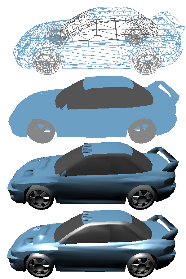
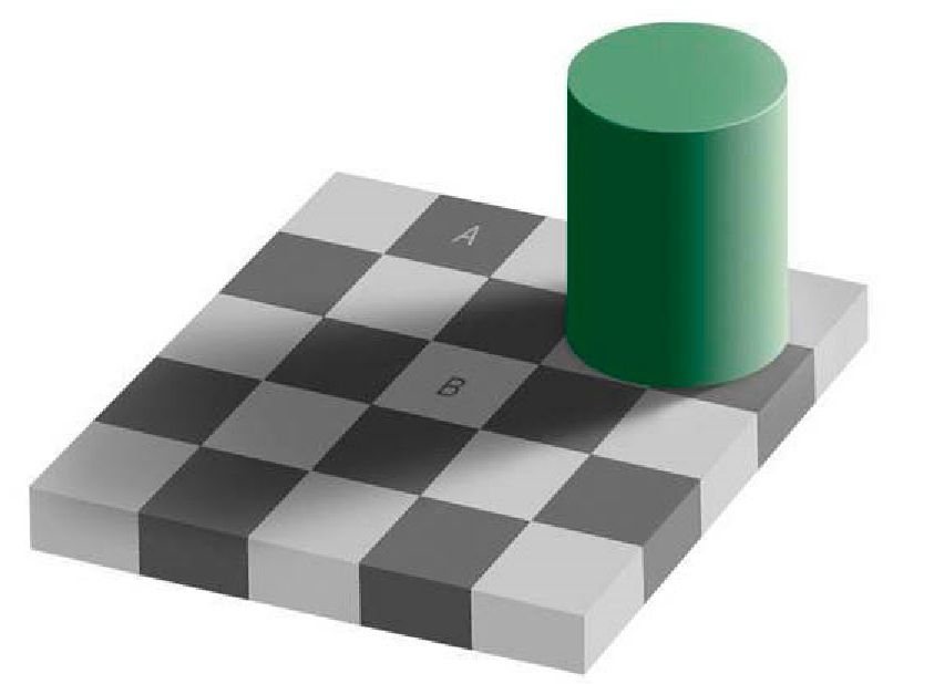
Realistic views of scenes are obtained by generating perspective projections with hidden surfaces removed and appropriate lighting and colouring applied to the model. A Shading model is used to calculate the intensity of light(colour) we should see when we view the surface. The exact colour of a surface when viewed depends on more than pigmentation; the amount of light striking the surface, the colour of the light, the angle the light strikes the surface, the orientation of the viewer and the texture of the surface all contribute to the actual colour we see (figs below). When we view an object what we see is light from light sources reflected from the surface.
The amount and direction of the reflected light depends on the properties of the surface. Some of the light striking a surface is abosorbed and not reflected. The amount of light reflected id usually different for different colours. This is a function of the reflectivity of the surface.
Light hitting a surface will be reflected in a multitude of different directions. The distribution of the reflected light is related to the material properties of the surface (or subsurface) .
Lighting is very important in presenting a realistic view of a scene in computer graphics.

In a scene, illumination from light emitting sources is reflected off multiple surfaces, these reflections combine to produce an approximately uniform illumination called ambient light. Ambient light in a scene appears to come equally from all directions.
Point lights are modeled as a light radiating equally from a single point in space, light from incandescent bulbs can be modeled successfully this way. The intensity of a point light reduces with further distance from the light.
Some light sources are sufficiently far away that the rays of light falling on the scene are parallel. These light sources can be mathematically modeled as infinitely far away and their distance does not effect their intensity. The sun can be simulated as directional light. Directional lights are easier to work with.
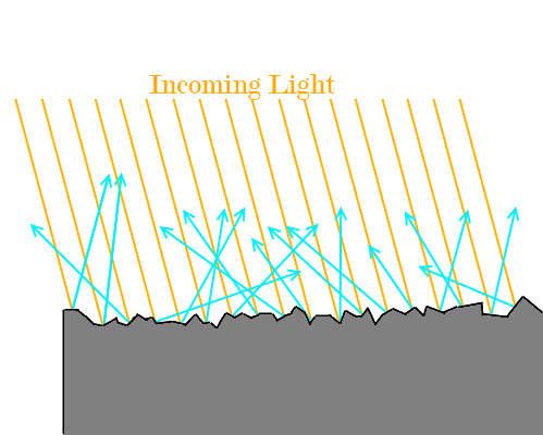
When light strikes a surface, most of it is scattered equally in all directions (figure below). This is called Diffuse reflection. The amount of diffuse reflection from a surface is primarily determined by the roughness or texture of the surface.
Ideal diffuse reflectors reflect light equally in all directions.
Ambient light comes equally from all directions and (diffusely)reflects equally in all directions, so the amount of ambient light reflected to the viewer is the same regardless of view position or object position.
If a surface is exposed only to ambient light then we can express the intensity of diffuse reflection as:
\[ I=R_{d}I_{a} \]
(where $R_{d}$ = Co-efficient of reflection of the surface (constant for a given surface $(0<=Rd<=1$ ), $I_{a}$ is the intensity of Ambient light).
The level of diffuse reflection of ambient light is similar in all directions. Highly reflective surfaces (bright white) have a $R_{d}$ near one, which means that almost all the incident light is reflected.
More realistic shading models will include illumination from light sources as well as ambient light. The calculation of diffuse reflection from a point source is based on Lambert's cosine law, which states that the intensity of reflected light is dependant on on the angle of illumination. When a surface is at a steep angle to the light rays, less light strikes the surface (figure below).
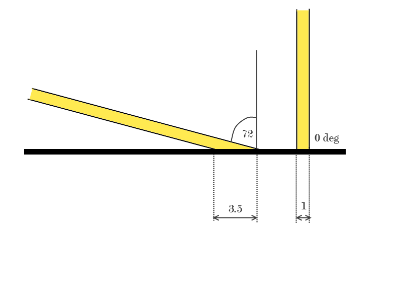
To simplify calculations we will assume that the light rays are parallel as they strike the surface (This is a good approximation for sources which are reasonably far away from the surface). We will describe the orientation of a surface with a unit normal vector $\vec{N}$ and the direction of the light source is the unit vector $\vec{S}$ .

The angle between the two vectors, $\theta$ , is called the angle of incidence. Lambert's law states that the amount of reflected light is proportional to the cosine of the angle of incidence. This can also be written as a dot product;
\[ \vec{N}.\vec{S}=\cos(\theta)|N||S|=\cos(\theta)\qquad(|N|=|S|=1) \]
A surface is illuminated by a light source only if the angle of incidence is between $0^{\circ}$ and $90^{\circ}$ .
Putting all of this together, we get the following equation for the intensity of diffuse reflection due to a directional light source source:
\[ I=R_{d}I_{s} (\vec{N}\cdot\vec{S}) \]
These equations assume we are dealing with mono-chromatic (white) light. In real world situations, light sources have different colours, and our model should be able to handle this. To accommodate the use of colours, our light intensity values and our reflectivity constants should become 3-Vectors, each vector contains values for the Red, Green and Blue components of the light source.
Now $I_{s}$ becomes the 3-vector ($I_{sr},I_{sg},I_{sb}$ ) and $R_{d}$ becomes ( $R_{dr},R_{dg},R_{db}$ ) where $I_{sr}$ represents the amount of red light in the source and so on. This breakdown is important as different surfaces reflect the colours by different amount; e.g. A surface with yellow pigmentation will reflect a lot of Red and Green, but will absorb most of the Blue light.
When viewing a shiny surface in the presence of a light source, bright spots on the surface are often seen. This is called specular reflection.

Specular reflection is only observed at certain viewing angles and depends on the orientation of the surface with respect to the viewer and to the light source. On a shiny surface, much of the incident light is reflected away from the surface at an angle similar to the angle of incidence.
For real surfaces, specular reflection is observed over a small range of angles around the angle of reflection. As the viewer moves away from the angle of reflection, the specular component decreases.


In figure below,$\vec{V}$ is a unit vector in the direction of the viewer and$ \vec{R}$ is a vector along the angle of reflection. When $\vec{V}$ and $\vec{R}$ coincide, the viewer sees maximum specular refection, as $\phi$ increases, the specular reflection decreases. For shiny surfaces the specular reflection is very bright but visible only over a small range of angles, for less shiny surfaces, the specular reflection is not as bright, but is visible over a wide range of angles.
A good approximation to the observed behaviour of specular reflection is the Phong Specular Model.
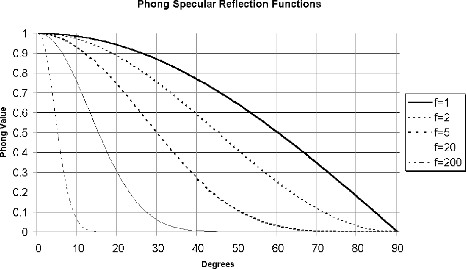
In the Phong model, the intensity of specular reflection is proportional to $\cos^{f}(\phi)$ , where f depends on the surface and ranges between 1 and 200. Very shiny surfaces have high values of f, as specular refection is exhibited over a small range of $\phi$. We know that $cos(\phi)=\vec{R}.\vec{V}$.
\[ I_{sp}=I_{s}R_{s}(\vec{R}\cdot\vec{V})^{f} \]
($I_{sp}$ = intensity of specular reflection, $R_{s}$ = co-efficient of specular reflection; $R_{s}$ is usually = $R_{d}$ ).
From the diagram above, we can see that the reflection vector is calculated as;
\[\begin{eqnarray*} \vec{R}&=&2(\vec{N}\cdot\vec{S})\vec{N}-\vec{S} \end{eqnarray*}\]Calculating $\vec{R}$ for each vertex can be costly. A refinement of this model is the Blinn-Phong specular model. Blinn observed that the vector $\vec{H}=\frac{\vec{S}+\vec{V}}{2}$ forms an angle ${\mathbf{\alpha}}$ with $\vec{N}$ such that $\alpha=\frac{\phi}{2}$ . Because of the linear relationship between $\alpha$ and $\phi$ we can amend the phong specular model like so;
\[ I_{sp}=I_{s}R_{s}(\vec{H}\cdot\vec{N})^{f'} \]
$\vec{H}$ is slightly easier to calculate than $\vec{R}$ . But if we use directional lighting (light source at infinity) and assume the viewer is at infinity (constant $\vec{S}$ , then both $\vec{H}$ is constant throughout the scene and can be calculated once per frame (it is not dependant on $\vec{N}$ . This results in a significant increase in rendering efficiency.
Lights emit a certain quantity of light per unit time. For a point-like light such as a light bulb, it emits this light radially, in all directions. The farther from the light source one gets, the more area that this must ultimately cover.
Light is essentially a wave. The farther away from the source of the wave, the less intense the wave is. For light, this is called light attenuation.
Attenuation is a well-understood physical phenomenon. In the absence of other factors (atmospheric light scattering, etc), the light intensity varies with the inverse of the square of the distance. An object 2 units away from the light feels the light with one-fourth the intensity. So our equation for light attenuation is as follows:
\[ \textrm{Attenuated Light}=\frac{L}{1.0+kr^2} \]
In this equation $r$ is the distance of the light from the object. The constant $k$ is used for unit correction (and to make things look right). The $1.0$ in the denominator is there to deal with objects two close to the light and to prevent divide by zero problems.
© Ken Power 1996-2016