3D graphics has become an indispensable part of the computer users landscape. Applications such as CAD, games and scientific visualisation allow the user to navigate, manipulate and interact with an approximation of a 3D world, usually through a two dimensional display. The demand of users and the goal of computer graphics researchers is to improve the accuracy and realism of this approximation.
In order to store, process and render 3D objects and scenes using computer graphics, contemporary real-time interactive 3D graphics systems utilize polygon meshes. A polygon mesh is a collection of vertices and polygons that define the shape of an object. Polygon meshes are flexible, easy to understand, allow for the encoding of detailed surface features and are naturally amenable to processing by computational methods.
Other representations are available, for example constructive solid geometry(CSG) and volumetric grids, these are used where interaction speed is not a priority or are used as an intermediate representation before being converted into a mesh.
Real world scenes can be arbitrarily complicated. Interactive system need a fast frame rate to provide an satisfactory user experience. Graphics hardware is limited in the number of primitives (e.g. triangles) which can be rendered in a given time. Computing for lighting and global effects further reduces the number of primitives which can be processed. Therefore implementers of graphics systems are faced with a tradeoff between rendering speed and scene complexity (or scene realism).
Important Reading: Watt & Policarpo; 3D-Games - The Economics of Polygon Meshes pp 53-62
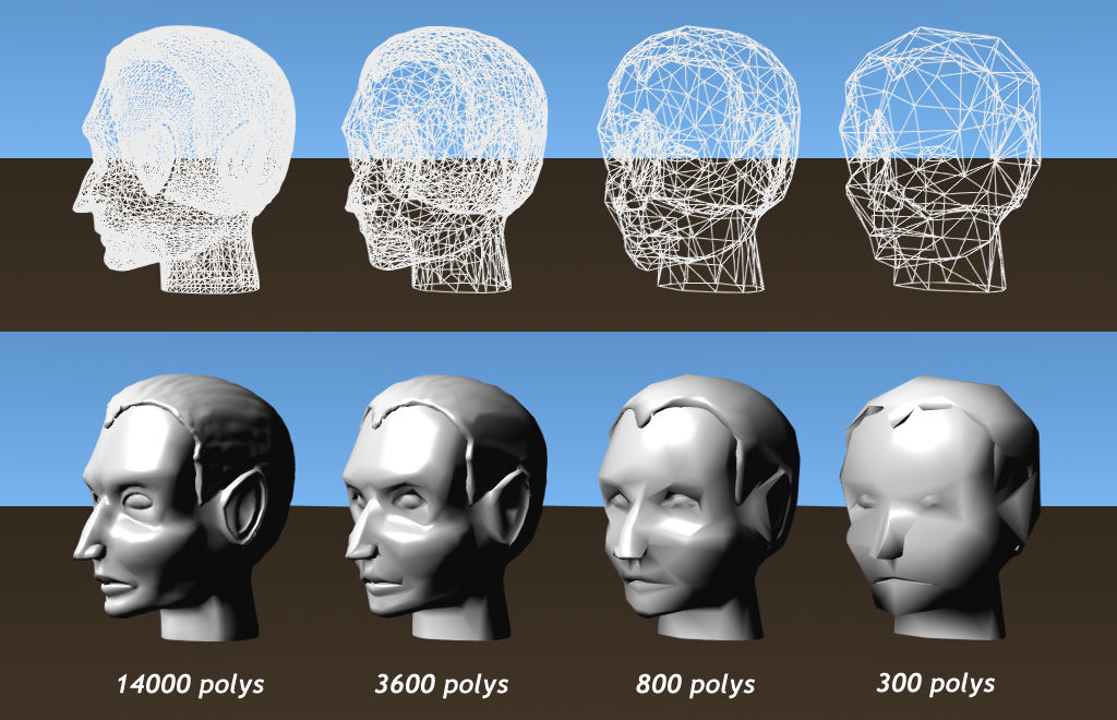
A naive approach to this problem would be to globally reduce the complexity(number of polygons) of the scene in order to improve frame rate. A more sophisticated approach introduced by James Clarke recognized the redundancy of using many polygons to render an object covering only a few pixels. Clarke described a scheme where each object had a number of different representations (Levels of Detail). The representation used to render the object was dependant on the expected screen space occupied by the object. Essentially, as an object moves away from the viewer in perspective projection system, increasingly simpler mesh(coarser approximations) can be used to render the object.
Early practitioners created LODs by hand, but this becomes impractical as models became larger and more complex. The advent of range scanners and medical imaging devices which can scan convert real objects in to multi-million polygon meshes created a need for automated level of detail creation.
An automated LOD procedure should be able to significantly reduce the number of polygons while maintaining a good approximation to its visual appearance. The fist simplification algorithms began to appear in the early 1990's and remains an active area of study today as researchers try to develop faster, more accurate and more usable techniques demanded by the graphics community.
Application of LOD over a wide variety of type of graphics applications has resulted in the development a number of approaches to LOD management. These approaches can be naturally catagorised into three distinct frameworks ; Discrete, Continuous and View Dependant
The traditional approach to LOD has been referred to as discrete LOD. A number of versions of an objects are created, each with a different level of detail during an offline process. At runtime an appropriate version is used to render the object. The choice of version used by the rendering engine determined by estimated screen space error or the need to reduce scene complexity to maintain frame rate or (usually) a combination of these two factors.
Discrete LODs are produced offline, therefore have the advantage of having no constraint on time required to generate the simplifications. The simplification can be further optimised to take advantage of certain features within graphical hardware. For these reasons Discrete LOD is the most widely used approach.
As processing is done offline, discrete LOD can not predict from what direction the object will be viewed, so the simplification process reduces detail uniformly across the model. In this case relatively large objects which have a large spatial range in the direction away from the viewer may have redundant detail in the parts of the model that are relatively distant. An additional problem is the rendering of silhouettes or the outline region of a projected object. The human eye visual system is very good in spotting discontinuities (straight edges and angles) in ostensibly continuous boundary.
A data structure encoding a continuous spectrum of detail is created offline. The key advantage of this approach is that the exact level of detail required for a model in a given situation can be quickly extracted from the data structure. The allows the engine to use only the exact number of polygons needed, freeing up polygons for other parts of the scene.
View Dependent LOD attempts to solve some of the problems mentioned in discrete LOD above. Areas of a single object can be rendered with different level of detail. Regions where visual fidelity is important (areas close to the viewer, silhouettes, perceptually important areas, etc.) can be rendered in high detail, while less important regions can be rendered coarsely. Terrain rendering is a field which benefits greatly. This approach gives is an ideal solution where the polygon budget is a priority, as polygons can be used where most needed.
The major drawback to View Dependant LOD is the fact that simplification needs to be done in real-time. In most situations the processing overhead required usually outweighs the gains in polygon efficiency.
In order to inform the application of simplification operators (see below), a measurement must be made of the estimated error caused by applying the operator. Knowledge of the error is also used by LOD management systems to determine which Model to render in a give situation.
Most systems use geometric based metrics. Geometric measure are concerned with maximum and average distance between corresponding vertices, vertices and closest surfaces or inter-surface distance. These type of metrics are particularly useful when deciding how to apply a local simplification operator.
Geometric error is an indirect surrogate for the error to be minimised, namely, the errors in the rendered image. In this scheme, the impact of simplification operators on the image fidelity was measured and the operator with the smallest effect on the image applied. This approach is very slow when compared to geometric algorithms, there are also potential problems caused by undersampling the visual space around the model. Finally, the LODs produced are dependant on rendering parameters (lights, shading model etc) and may be sub optimal for different rendering conditions.
The goal of mesh simplification is to reduce the complexity of the mesh (number
of polygons) while maintaining the maximum visual fidelity. A large number of
local simplification operations have been described in the literature. An operator
can be applied to any part of the mesh. The choice of where and how to apply
an operator is informed by measuring the error e between
the original and simplified mesh. The typical approach is to apply the operator
which minimises e. The measurement, more accurately,
the estimation of e is a difficult problem in itself
and will be discussed later.
Repeated application of local simplification operators will produce a mesh of
desired complexity.
Edge Collapse removes an edge (and its two vertices and two triangles) from the mesh. A new vertex is created, then edges in the neighborhood (edges which share endpoints) of the removed edge are connected to the new edge. A half edge collapse, is an edge collapse in which one of the original vertices is preserved as the 'new' vertex.
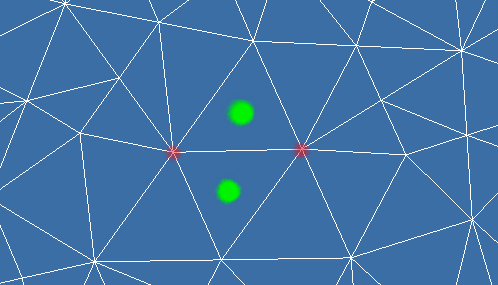
Edge collapse can cause mesh foldovers. Mesh foldover can cause undesirable effects such as discontinuities in texturing and lighting. A mesh foldover is detected by comparing the normals of the triangles before and after the edge removal. A large change in the normals(usually > 90 degrees) characterises a mesh foldover.
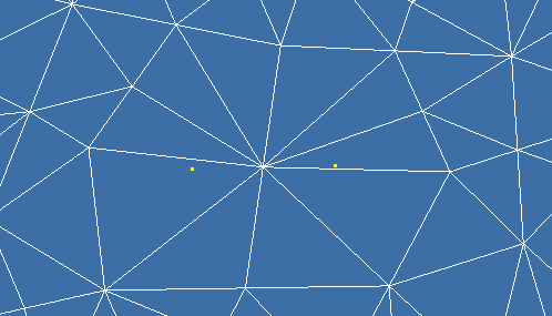
Vertex Pair collapse amalgamates two unconnected vertices. The effect is similar to the collapse of an imaginary edge joining the two points, This is useful for filling holes in the mesh. As the number of unconnected pairs of vertices in a mesh is quite large, O(n2), heuristics have been developed to reduce the number of candidates.
A Triangle collapse removes a triangle, replacing it with a new vertex. The neighborhood of the new vertex will be neighborhood of the triangles original 3 vertices.

Cell Collapse collapses all vertices in a given area to one vertex. The area can be based on a regular grid or a volume surrounding vertices.
Vertex removal removes a vertex, its edges and triangles, then re-triangulates the resulting hole.
Polygon Merging removes a number of adjacent (almost) coplanar faces and re-triangulates the hole.
Global Simplification operators consider the entire topology of the object fine tuning the parameters of a global operator will produce a mesh within specified error bounds. Techniques here include Volumetric processing and simplification envelopes.
Important Reading: Luebke et al. Level of Detail- Gaming Optimizations. pp 151-183