Last Updated October 13, 2009
How are 3D objects represented in a computer?
The representations need to be space efficient and amenable to quick computational processing.
We need to manipulate the objects computaionaly; move, rotate, articulate, deform, strech...

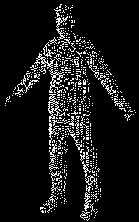
An unstructured set of 3D point samples. Aquired from a range finder, laser, computer vision, 3D Scanner. Point clouds themselves are generally not directly usable in most 3D applications, and therefore are usually converted to triangle mesh models.
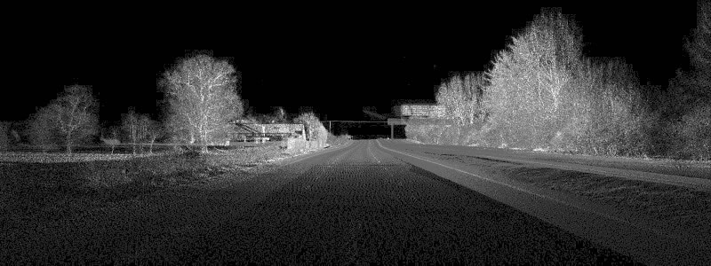
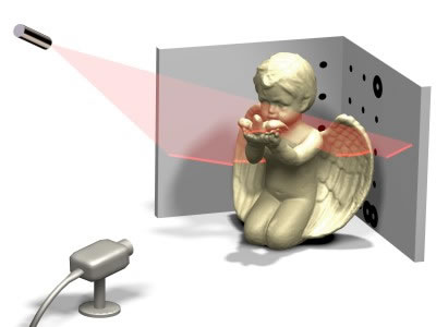
Range imaging is the name for a collection of techniques which are used to produce a 2D image showing the distance to points in a scene from a specific point, normally associated with some type of sensor device.
A polygon soup is an unstructured set of polygons, usually created using an interactive modelling system (Blender, 3DStudio Max etc). The soup usuallyt consits of a list of unconnected triangles forming the skin of an object.
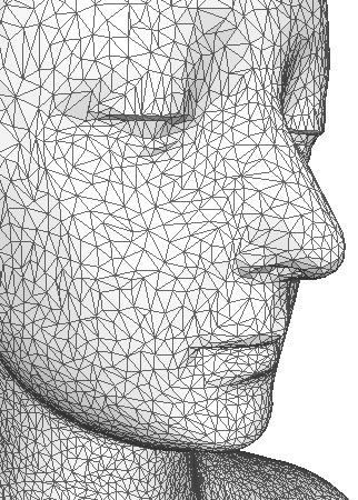
Connected set of poygons (typically triangles).
Skeleton
Scene Graph
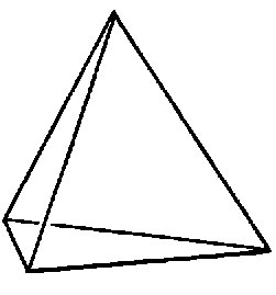
With a wireframe model we specify a set of points in space and we connect various pairs of these points to form edges. This representation only suggests the actual shape and doesn't really look solid. We need a method to make an object look solid and to be able to colour it's surface.
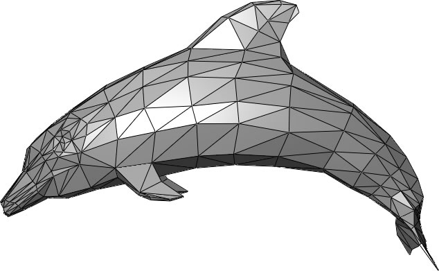
We can do this with polygon mesh models. A polygon mesh approximates the surface shape of an object by specifying a set of points in space these points representing vertices of various polygonal faces.
Consider the mesh in the figure above, we have 8 vertices and 6 faces(polygons). A list of vertices for a polygon is created by looking at the polygon from the outside, listing the vertices in a counter-clockwise direction until a complete circle is made.
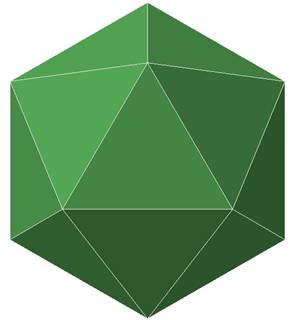
This kind of mesh is known as a polyhedron>, which is a closed mesh (encloses a definite volume) and all the faces are planer>. A polyhedron can be used to represent almost any solid, but if the solid is highly curved, we must use a large number of faces to achieve the illusion of roundness and smoothness. In a polyhedron, no edges can be shared by more than 2 faces.
There are 3 main polygon mesh representations in use:
The vertices are stored in counter clockwise order. There are edges between each pair of vertices and between the first and last vertices. This representation is not space efficient, because a shared vertex, will be stored many times. In a Cube for instance, each vertex is shared by 3 faces. Each edge is drawn twice. Also it is unclear from this representation, which faces are connected to which, this make manipulation difficult.
In the representation we have a vertex list, which contains all the vertices in the mesh.
And a polygon is defined as a list of indices or pointers into the vertex list. e.g.
Each vertex is stored once. But each edge is stored twice and it is difficult to find polygons that share an edge.
Again we have a vertex list V, but we also have an edge list E, in which each edge occurs just once. Each edge is stored as a pair of pointers into the vertex list, each edge also contains pointers to the polygons which share the edge. Polygons are defined as lists of pointer to the edge list.
To draw a wire frame in this representation, just draw all the edges in the edge list.
© Ken Power 2009