elevation, plans and sections of the Pantheon in Rome
Last Updated November 19, 2013
Converting a model or a scene from a 3D representation (vertices with (x,y,z) coordinates) to 2-Dimensions is called graphical projection (or just projection). A 3D scene is projected on to an infinite flat plane called the viewplane. This process is nessesary whenever a 3D object is to be depicted onto a 2D surface (printing, computer screen, casting a shadow...).
Projections are carried out by transferring points in the scene onto the viewplane.
A special point known as the the centre of projection (also known as the eye or camera) defines the type of projection to be used.
A line, called a projection ray is created through the centre of projection and a point in the scene. The point is projected by moving it to intersection of the projection ray and the viewplane. This process is carried out for all points or vertices in the scene. After this stage all the points in the scene are lying on the 2D plane, ready to be trandsfered to corresponding points on a computer screen or printer paper.
In a parallel projection, the eye (or centre of projection) is at infinity, so the projection rays are parallel (hence the name). In order to avoid working with points at infinity, it is often more convienient to specify a projection vector. In this case the rays of projection are cast through the point and parallel with the projection vector.
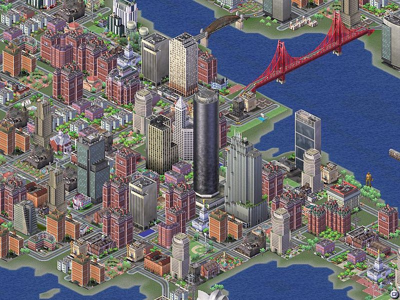
With all types of parallel projection, objects drawn with isometric projection do not appear larger or smaller as they extend closer to or away from the viewer. While advantageous for architectural drawings where measurements need to be taken directly, the result is a perceived distortion as it is not how our eyes or photography normally work.
It also can easily result in situations where depth and altitude are difficult to gauge.
When the projection vector is perpendicular to the viewplane, this produces an orthogonal projection. The projection rays all intersect the viewplane at right angles. A feature in common with all orthogonal projection is that they lack "perspective", object do not appear smaller with distance from thew viewer.
The simplest orthogonal projections are created by aligning the viewplane with planes of scene. This is used to produce front elevation, side elevation or plan view of an object or scene. A special projection, called a section (from cross-section), is produced when parts of the scene are removed so as to see inside the object.
Architects and engineers often use this type of projection as lengths and angles are acurately depicted.
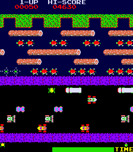
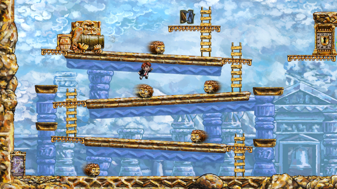
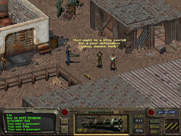
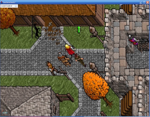
These types of projection are seen in certain side scrollers and some games with a top down view. Although it is arguable if these games really use a projection as the scene is stored internally as a 2D scene.
The plan and elevation projections are produced creating a view transformation with the eye at the origin and the "look at" point (or directrion of the camera) on one of the 3 main axes. A section is produced bycontroling the near and far planes (see view volume, later)
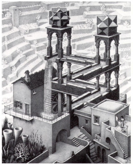
Foreshortening refers to the visual effect or optical illusion that an object or distance appears shorter than it actually is because it is angled toward the viewer. This is a problem with all kinds of projection.


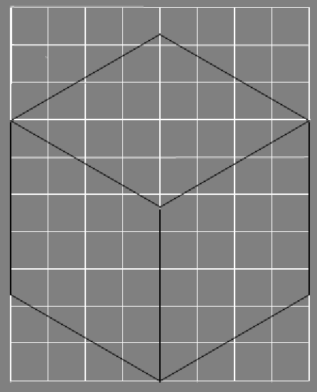
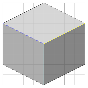
The plane and elevation orthographic projections show only show one side of an object, effectively they show only two of the object' axis. If the viewplane is placed so that all 3 object axis are visible and equally scaled, this is an isometric projection. Isometric means "equal measure", so called because all the sides of a cube have the same length when projected. Another way of looking at it is that all the axes are foreshortened equally.
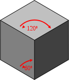
To achieve an isometric viewing transformation, the camera is rotated by $45^\circ$ around the vertical axis and by $\arcsin(\tan 35^\circ)$ about the horizontal. A simpler way of acheiving the same effect is to place the eye at the origin and look at the point $(-1,-\sqrt{2},-1)$.
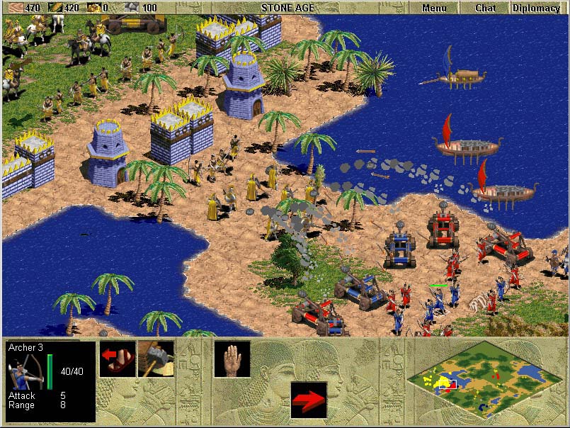
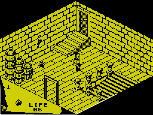
Technically the the games shown above are not isometric but dimetric projections.
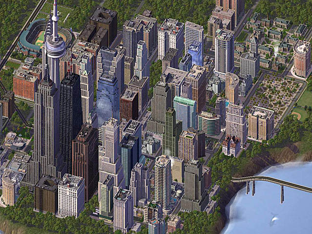
In video games the isometric projection is modified slightly to make it fit better in the regular grid of pixels. Edges are drawn by moving two pixels right and one pixel up. This produces a line with a slope of 0.5 which produces an angle of $26.57^\circ$.
In a dimetric projection only two axes have equal scalling, the third axis (usually the vertical) is scaled differently. Sometimes this is called the 1:2 isometric projection.
The viewplane is positioned so that all three axes are scaled differently (appear unequally foreshortened) .
The trimetric projection lack the symmetry of dimetric projections, so looks more natural, less "computer generated".
Advantages of Axonometric projections.
Disadvantages
Oblique projections are parallel projections created when the direction of projection is not perpendicular to the view plane. This type of projection has not been popular in games becuase it makes images appear distorted. Sphere appear as ovals, one side of a cube is square, the other side can be a rombus.
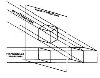
One type of oblique projection which has been used in games is the Cabinet projection. One face of the object is parallel with the viewplane, the receeding axis is drawn either $30^\circ$ or $45^\circ$ away from the horizonal. The receeding axis is foreshortened by 50% to look more natural (distances along the receeding axis are scaled by a half).


As discussed before, the viewplane is the infinite plane (usually lying on the u-v axes of the viewing coordinates). Obviously, an infinite plane cannot easily be accomodated on a finite rendering device, so a Clipping Window is defined.
The clipping window is a rectangle on the viewplane, aligned with the $u \& v$ axis. It is normally defined by two points $(w_l, w_b) \& (w_r, w_ t)$, describing the bottom-left and top-right points of the window. Only parts of the scene projected into this rectangle will be visible in the final image. All other parts of the scene will be clipped (removed).
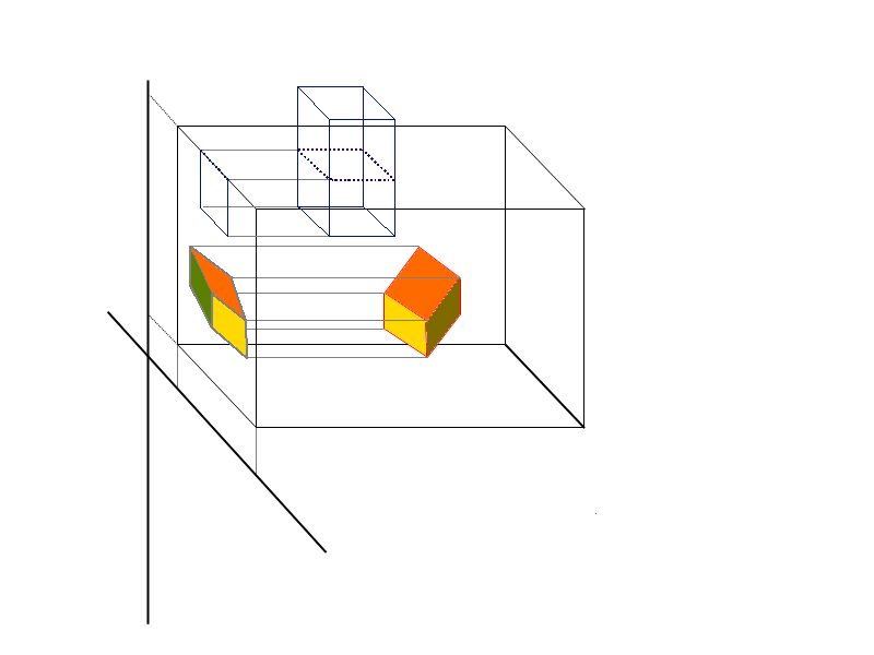
Because projection lines are perpendicular to the viewplane, the four edges of the clipping window define 4 planes perpendicular to the viewplane forming an infinite clipping region. The extent of this clipping region usually needs to be limited along the n-axis, by introducing two further planes, parallel to the viewplane. These are the near & far clipping planes. These allow parts of the scene to be removed which are too far away or in front of parts of the scene we wish to display.
The six plane defined form a finite volume called the view volume, in the shape of a rectangular parallelepiped. All parts of the scene outside the view colume will be clipped at a later stage.
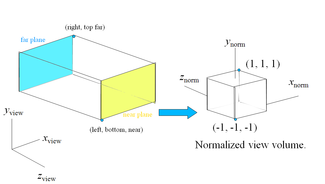
The view volume, defined by two points $( w_l, w_b, near) \& (w_r, w_t, far)$. The view volume needs to be transformed to a cube, centred on the origin, to create the Normalized View Volume This is done to simplify later stages of the rendering pipeline;
The normalization transformation is a matrix which will map a point from the view volume to the normalized view volume. This is a concatonation of two tranformations;
The centre of the view volume is at $(\frac{w_l+w_r}2{}, \frac{w_b+w_t}{2}, \frac{near+far}{2})$. Therefore the translation matrix is;
\[ \mathbf{\hat{T}}=\left(\begin{array}{ccccc} 1&0&0&-\frac{w_r+w_l}{2}\\ 0&1&0&-\frac{w_t+w_b}{2}\\ 0&0&1&-\frac{near+far}{2}\\ 0&0&0&1 \end{array} \right) \]
The width of the viewvolume is $w_r-w_l$, the height of the viewvolume is $w_t-w_b$, the depth is $far-near$
To scale a value from one range of values to another, we divide by the size of the original range and multiply by the size of the new range.
Therefore the scaling matrix required is;
\[ \mathbf{\hat{S}}=\left(\begin{array}{ccccc} \frac{2}{w_r-w_l}&0&0&0 \\ 0&\frac{2}{w_t-w_b}&0&0 \\ 0&0&\frac{2}{far-near}&0\\ 0&0&0& 1 \end{array} \right) \]The normalization matrix is a combination of the the two transformation matrices above;
\[ \mathbf{\hat{N}}=\mathbf{\hat{S}} \mathbf{\hat{T}}= \left(\begin{array}{ccccc} \frac{2}{w_r-w_l}&0&0&-\frac{w_r+w_l}{w_r-w_l} \\ 0&\frac{2}{w_t-w_b}&0&-\frac{w_t+w_b}{w_t-w_b} \\ 0&0&\frac{-2}{far-near}&-\frac{far+near}{far-near} \\ 0&0&0& 1 \end{array} \right) \]
The plan and elevation projections are produced creating a view transformation with the eye at the origin and the "look at" point (or directrion of the camera) on one of the 3 main axes. A section is produced by controling the near and far planes.
For the isometric and dimetric projections the camera is pointed at a certain point to render the view.
The final stage in the projection is to specify a view volume and transorm the viewvolume to the normalised view volume.
To transfer a point $(u,v,n)$from the view volume to the viewplane, simply take the $(u,v)$ coordinates. The depth coordinate($n$) will be retained to aid in hidden surface removal at a later stage.
© Ken Power 2011