A scene-graph is a data structure commonly used by 3D rendering applications. The scene graph is the core data structure around which a graphics engine is built.
The scene-graph is structure that arranges the logical and spatial representation of a graphical scene. There is not an accepted formal definition of what exactly can and can't be contained in a scene graph, as implementers often adapt the basic principles of scene graphs for a particular situation.
Scene-graphs are a collection of nodes in a graph or tree structure, normally a directed acyclic graph (DAG).
The effect of a parent is apparent to all its child nodes - An operation applied to a group automatically propagates its effect to all of its members.
In many programs, associating a geometrical transformation matrix at each group level and concatenating such matrices together is an efficient and natural way to process such operations. A common feature, for instance, is the ability to group related shapes/objects into a compound object which can then be moved, transformed, selected, etc. as easily as a single object.
Scene graphs normally employ two types of node;
An applet allowing the user to build and visualize a simple scenegraph can be found here.
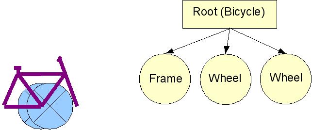
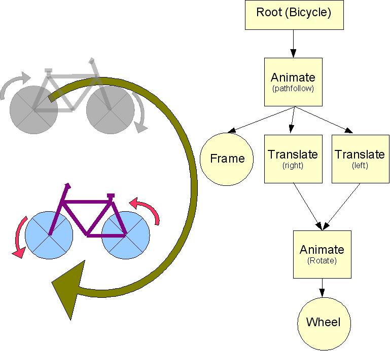
Consider a bicycle, made up of a frame and two wheels, this situation could be represented as follows (We are assuming that we have some rendering code for the frame and wheels;
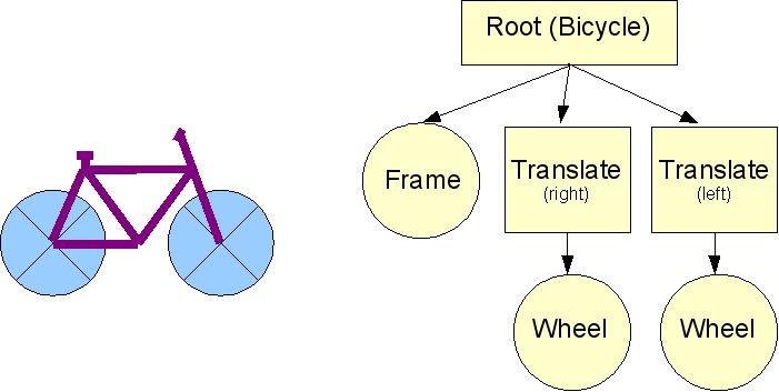
This image isn't quite right. Most objects and elements of models are drawn at the origin. In order to move the wheels to their correct position, we need to add transformation nodes to the scene;
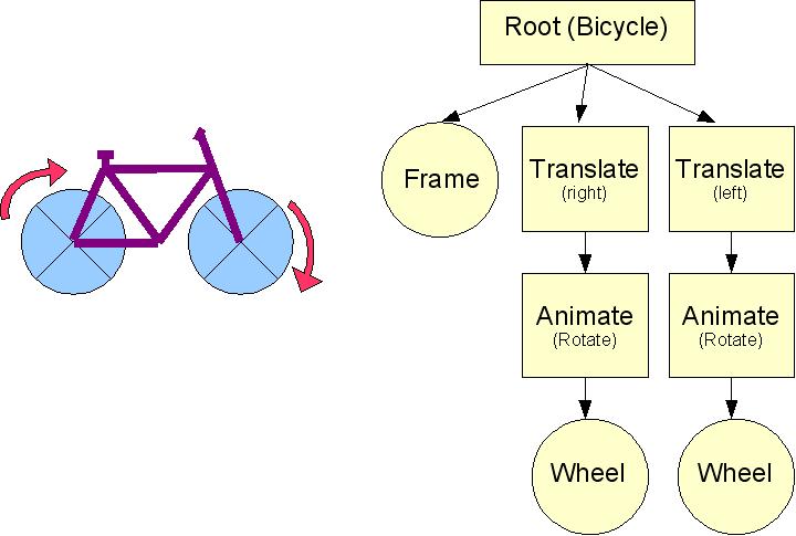
A scene graph can contain animation nodes, which apply a transformation depending on the time, these can be used to animate elements of the scene;
The action of any node is applied to all of its children, so, if we insert a node which implements path following, we can cause the whole model to move along a specified path. Like all computer animation, this movement is an illusion, the scene is drawn with slightly different positional parameters each frame.
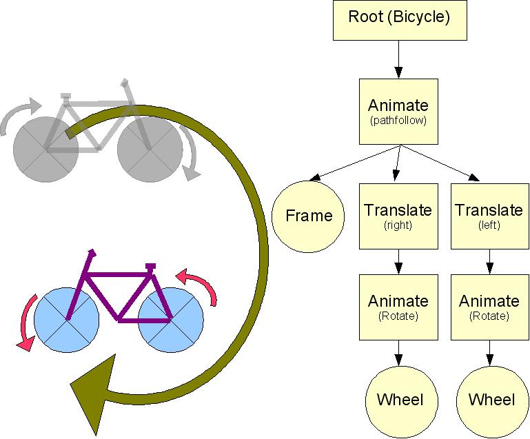
Finally (for this example), a scene graph may reuse a common component (sub tree). In this example, we assume that both wheels will always be rotating at identical speeds.
Nodes are ideally implemented as a set of inherited classes. One function which must be present for all the classes is Render(). This function causes the execution of the 'intent' of the node. Render() usually works by making calls to the Graphics API (OpenGL, Direct3D, etc).
Another function normally present in all nodes, is Update(), which requests a node to incrementally update its position or state since the previous frame, based on the game rules
The Graph is executed in a recursive depth-first fashion.
Group nodes typically change the state of the rendering engine, by setting the viewing matrix or turning on a light, or maybe changing the current colour. The effect of a group node only applies to the children of the group node. The following pseudo code illustrates the Render() action of a group node;
 	Save current state

	For each child node
 		child->Render()

	Restore saved state
Developers have implemented dozens of different node types in order to implement many different effects. This is a list of the type of nodes necessary for a basic scenegraph.
A simple leaf node represents a trivial drawing primitive, line, polygon, sphere, cylinder etc.
Represents a complex object, typically loaded from a file. A scene graph must implement instancing, allowing a single model to be reused a number of time throughout the scene. A complex leaf normally encapsulates code to load and store data from a file.
These apply transformations to all the children
Change attributes of the Rendering system. Any changes apply only to the children
A rotation transformation, but rotating by an increasing amount each time. The increase rate is defined in degrees per second
A sequence of points defines a path in space. Objects in the subtree will follow this path over a specified period of time. A number of types of path following are possible;
Most models are composed of a number of key frames, defining intermediate poses in a set piece movement (e.g. walking) . This node will interpolate the model between the keyframes.
A group node, containing a number of subtrees, but only one subtree is rendered. Used to represent an object with different states, e.g. a character in a FPS game could be;
Scene graphs can be used to speed up collision detection, by incorporating a bounding volume at each node. A bounding volume is a defined region of space in which all the objects in the node's sub-tree reside. If an object does not intersect with a high level bounding volume, it cannot intersect any object below that node in the hierarchy.
The bounding volumes are calculated by performing a reverse traversal of the tree, merging the bounding volumes of children to create a bounding volume for the parent.
A scene graph used this way is called a Bounding Volume Hierarchy (BVH). Some game engine keep the BVH and scene graph separate.