Last Updated November 12, 2013
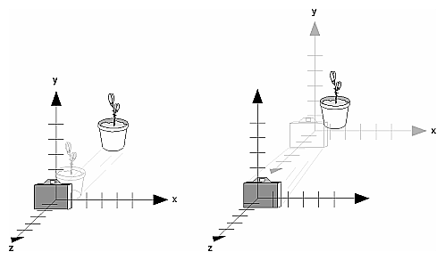
A viewing transformation changes the position and orientation of the viewpoint. In a camera analogy, the viewing transformation positions the camera tripod, pointing the camera toward the model. Just as you move the camera to some position and rotate it until it points in the desired direction, viewing transformations are generally composed of translations and rotations. Also remember that, to achieve a certain scene composition in the final image or photograph, either you can move the camera, or you can move all the objects in the opposite direction. Thus, a modeling transformation that rotates an object counterclockwise is equivalent to a viewing transformation that rotates the camera clockwise, for example.
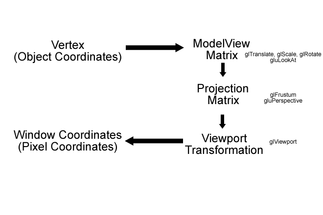
Both modeling (moveing model around) and viewing (camera control) is manipulated by the ModelView Matrix.
Each model vertex is transformed(multiplied) by the current ModelView Matrix as it is entered into the system by glVertex*(). This operation results in the vertice's final position in 3D space.
The ModelView Matrix, is in turn manipulated by the transformation functions (glScale, glRotate & glTranslate). The transformation functions simply muliply the Modelview Matix (if it is currently selected) by an appropriate matrix representing the transformation.
The ModelView Matrix is can also be manipulated by the various viewing (camera) transformations (e.g. gluLookAt).
Because of this intimate relationship between Modeling and Viewing, OpenGL combines both operations in to a single matrix, the ModelView Matrix.
You can accomplish a viewing transformation in any of several ways, as described below. You can also choose to use the default location and orientation of the viewpoint, which is at the origin, looking down the negative z-axis.
Use one or more modeling transformation commands (that is, glTranslate*() and glRotate*()). You can think of the effect of these transformations as moving the camera position or as moving all the objects in the world, relative to a stationary camera.
Use the function gluLookAt() to define a line of sight. This routine encapsulates a series of rotation and translation commands.
Create your own custom function that encapsulates rotations and translations. Some applications might require custom routines that allow you to specify the viewing transformation in a convenient way. For example, you might want to specify the roll, pitch, and heading rotation angles of a plane in flight, or you might want to specify a transformation in terms of polar coordinates for a camera that's orbiting around an object.
The pupose of the projection transformation is to define a viewing volume. The shape of the viewing volume has two important effects;
In order to make changes to the Projection matrix, it must be made current. It is normally a good idea also to reset the matrix before applying changes.
 glMatrixMode(GL_PROJECTION);
    glLoadIdentity();

    //set up a 3D Perspective View volume
    //gluPerspective(90.f, 1.f, 1.f, 300.0f);//fov, aspect, zNear, zFar

    //set up a  orthographic projection same size as window
    //this means the vertex coordinates are in pixel space
    glOrtho(0,800,0,600,0,1); // use pixel coordinates
With an orthographic projection, the viewing volume is a rectangular parallelepiped,
or more informally, a box (see Figure 3-13 ). Unlike perspective projection,
the size of the viewing volume doesn't change from one end to the other, so
distance from the camera doesn't affect how large an object appears. This type
of projection is used for applications such as creating architectural blueprints
and computer-aided design, where it's crucial to maintain the actual sizes of
objects and angles between them as they're projected.
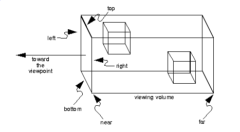
The command glOrtho() creates an orthographic parallel viewing volume. The right, left, top, bottom, near & far clipping planes are specified.
glOrtho desctibes a transformation that produces a parallel projection (this is just the normalization matrix). The current matrix (usually GL_PROJECTION) is multiplied by this matrix.
with perspective projections, the farther an object is from the camera, the smaller it appears in the final image. This occurs because the viewing volume for a perspective projection is a frustum of a pyramid (a truncated pyramid whose top has been cut off by a plane parallel to its base). Objects that fall within the viewing volume are projected toward the apex of the pyramid, where the camera or viewpoint is. Objects that are closer to the viewpoint appear larger because they occupy a proportionally larger amount of the viewing volume than those that are farther away, in the larger part of the frustum. This method of projection is commonly used for animation, visual simulation, and any other applications that strive for some degree of realism because it's similar to how our eye (or a camera) works.
The command to define a frustum, glFrustum(), calculates a matrix that accomplishes
perspective projection and multiplies the current projection matrix (typically
the identity matrix) by it. Recall that the viewing volume is used to clip objects
that lie outside of it; the four sides of the frustum, its top, and its base
correspond to the six clipping planes of the viewing volume, as shown in Figure
3-11 . Objects or parts of objects outside these planes are clipped from the
final image.
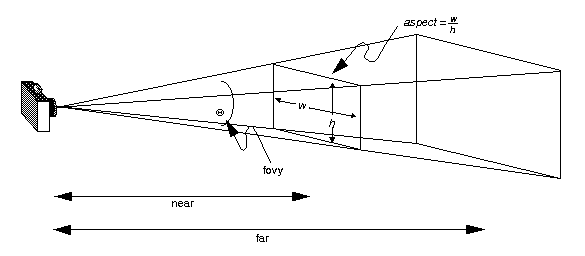
Although it's easy to understand conceptually, glFrustum() isn't intuitive to use. Instead, you might try the utility library routine gluPerspective(). This routine creates a viewing volume of the same shape as glFrustum() does, but you specify it in a different way. You specify the angle of the field of view in the x-z plane and the aspect ratio of the width to height (x/y). (For a square portion of the screen, the aspect ratio is 1.0.) These two parameters are enough to determine an untruncated pyramid along the line of sight, as shown in Figure 3-12 . You also specify the distance between the viewpoint and the near and far clipping planes, thereby truncating the pyramid.
//calculate new prespective and aspect ratio
gluPerspective(45.0f, 							// field of vision (fov)
				(GLfloat)width/(GLfloat)height,		//aspect ratio
				1.0f,								// near plane
				1000.0f								//far plane
				);
This application demonstrates the use of the projection matrix
The Viewport is the area on screen (within a Window) where the scene is drawn. This is usually set to be the same size as the client are of the application window;
glViewport(0,0,width,height); // set new viewport size
However, OpenGL will allow you to have two or more viewports in which you can render different views of the same object, or even different objects.
© Ken Power 2011