Watt, A. & Policarpo, F. 3D Games Realtime Rendering, Vol 1. Addison-wesley, 2001. Ch.15.
Watt, A. & Policarpo, F. 3D Games Realtime Rendering, Vol 1. Addison-wesley, 2001. Ch.11.
Welsh, T. Parallax
Mapping with Offset Limiting: A PerPixel
Approximation of Uneven Surfaces
Reflection mapping. (2006, September 26). In Wikipedia, The Free Encyclopedia. Retrieved 11:37, October 6, 2006, from http://en.wikipedia.org/w/index.php?title=Reflection_mapping&oldid=77872034
Randima Fernando and Mark J. Kilgard, The Cg Tutorial: The Definitive Guide to Programmable Real-Time Graphics Addison Wesley Professional
Channa, K. Light Mapping - Theory and Implementation. Retrieved October 7, 2006.
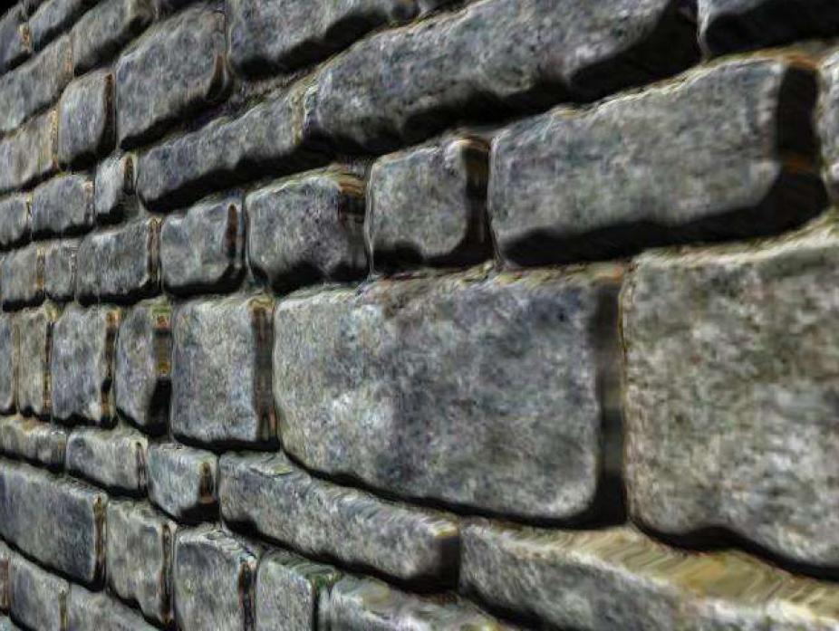
Bump mapping allows the surface to appear wrinkled or dimpled without the need to geometrically model the undulations. The basic premise is to perform the lighting calculations as if the bumps and hollows were present in the geometry.
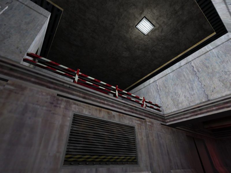
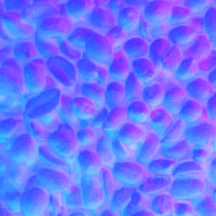
The most common form of bump mapping is normal mapping. A normal map is mapped to a surface just like a texture map. A normal map is a regular grid, each element of the grid contains a vector describing the normal at that point. When lighting calculations are performed at a point on a surface, the normal from the corresponding point on the normal map is used instead of the normal of the underlying face.
Normal maps are often stored in image files, with the RGB channels of each pixel storing the XYZ values of each normal.
A normal map is usually associated with a conventional texture map. The normal map is there to ensure that the texture is lit 'correctly'
(See here how to create normal maps from real life objects, using photographs from several angles and some photoshop tricks)
Nvidia has a free tool to generate normal maps from very hi-res models
Normal map coordinates are generated in the same way as texture map coordinates, an interpolation scheme is used to find the normal map coordinates for a point an a surface.
The lighting calculation is basically a dot product of the the light direction vector and the surface normal. For the calculation to be carried out these two vectors must be in the same coordinate space. It doesn't matter which space we use. world, view & clip space are not useful because each time the object or camera moves, the normals in the map need to transformed for the new space.
A much better space to do the lighting calculations is in 'texture space'. In texture space, the texture lies on the s-t plane. Of course the light direction vector must be recomputed into texture space.
Gamasutra article on Texture spaces
Normal mapping in XNA and HLSL
Displacement mapping is related to bump mapping in that it also uses a height map to model surface perturbations. The difference, however, is that displacement mapping actually modifies the surface geometry, whereas bump mapping only affects the normal vectors. In other words, displacement mapping adds geometric detail to your mesh. Hardware-accelerated displacement mapping, however, is still in its infancy.
You could displace vertices by reading the displacement map in the vertex shadier and moving the vertex in the direction of its normal. Even if you have a video card that can do this, however, you still need the actual vertices to displace, and preferably lots of them. Without some sort of adaptive tessellation scheme, the polygon counts required to get good-looking displacement mapping would be overwhelming. There would also be precious little benefit in doing the displacement on the fly, unless you need the displacement map itself to be generated on the fly as well. In all other cases, the displacement might as well be applied offline.
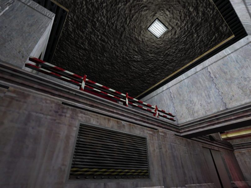
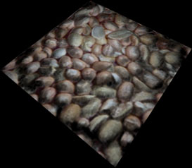
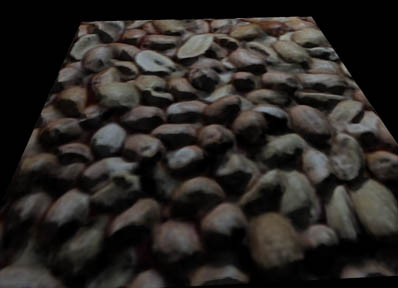
A cheap alternative to displacement mapping is parallax mapping. Parallax mapping uses a height map to attempt to calculate where the eye vector intersects the simulated surface. Parallax mapping does not change the underlying geometry.
A height map is a texture map representing a displacement for each point on the surface. It is usually stored in the alpha channel of normal maps.
Due to parallax effects, the texture coordinate based on the eye vector intersecting the polygon needs to be adjusted to take account of the surface undulations. The adjustment is called an offset and is calculated as follows; construct a plane parallel to the surface polygon at the height of the height map for the original texture coordinates (T0). The point of intersection of the eye vector and this plane gives the 'real' texture coordinates (Tn).
This technique makes the assumption that the height at T0 is the same as the height at Tn. But this is rarely true. The assumption causes two problems;
A solution to both these problems is to limit the magnitude of the offset to the height at T0.
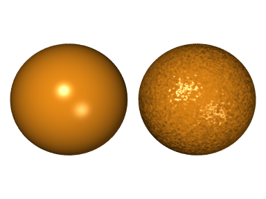
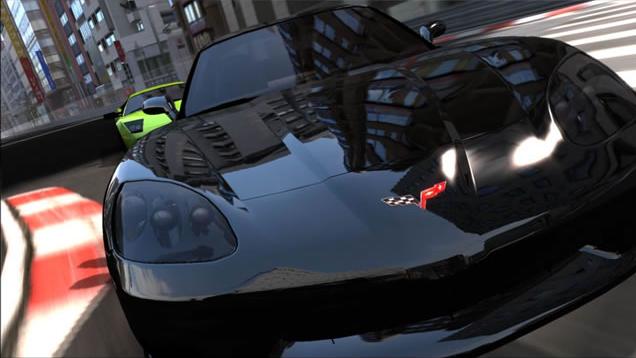
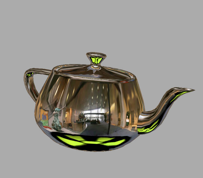
Sometimes called reflection mapping, environment mapping simulates reflections off shiny objects by pre calculating a texture map based on the object's environment.
Proper reflections from 3D surfaces require expensive raytracing to compute. Raytracing involves bouncing a ray from the surface at the reflection direction and perform an intersection test with the world to determine the object being reflected. This process is infeasible for realtime graphics .
Instead, a texture of the surroundings, computed, off-line is applied to the object.
Problems with environment mapping
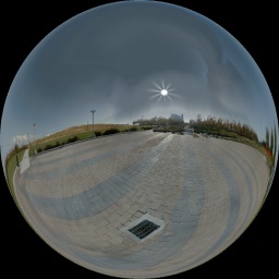
The original type of environment mapping involved creating a spherical map from a particular viewpoint. The reflection vectors from the object are mapped to the surface of the sphere to determine texture coordinates. The biggest drawback with this approach is that the sphere map is only valid for one viewing direction and needs to be recreated for every movement of the viewer.
Images of the sphere mapping process.
This is the technique favored by most real-time applications.
A cubic map is constructed from 6 orthogonal views from a given viewpoint. This map should not have seams.

During rendering, a reflection ray from the object is examined to determine which sub-map (which of the 6 squares) it intersects by comparing the reflection vector to the unit cube extents.
Determine point of intersection to retrieve texture coordinates.
If point of intersection is x,y,z on the +ive y face, the the texture coordinates are (x,z).
Normally the texture coordinates are explicitly calculated for the vertices of a polygon and interpolated using conventional texture mapping.
A problem which can occur is for vertices of a polygon to map to different faces of the map. In this case the polygon needs to be re triangulated so that each triangle is constrained to a single sub-map.
We assume that the environment is infinitely distant from the object.
The reason for the assumption is that environment maps are accessed solely based on a 3D direction. Environment mapping has no allowance for variations in position to affect the reflected appearance of surfaces. We examine only the reflection vector. If everything in the environment is sufficiently far away from the surface, then this assumption is approximately true.
In practice, the visual artifacts that result when the environment is not sufficiently distant typically go completely unnoticed. Reflections, particularly on curved surfaces, are subtle enough that most people fail to notice when a reflection is not physically accurate. As long as reflections match the coarse colouration of the environment and change appropriately with the curvature of the surface, surfaces rendered with environment mapping appear believable.
Ideally, every environment-mapped object in a scene should have its own environment map. In practice, objects can often share environment maps with no one noticing.
In theory, you should regenerate an environment map when objects in the environment move or when the reflective object using the environment map moves significantly relative to the environment. In practice, convincing reflections are possible with static environment maps.
With an environment map, an object can reflect only the environment; it cannot reflect itself. Similarly, do not expect multiple reflections, such as when two shiny objects reflect each other. Because an environment-mapped object can reflect only its environment and not itself, environment mapping works best on convex or mostly convex objects—rather than more concave objects.
Because environment mapping depends solely on direction and not on position, it works poorly on flat reflective surfaces such as mirrors, where the reflections depend heavily on position. In contrast, environment mapping works best on curved surfaces.
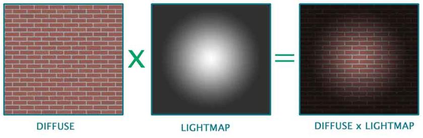
A light map is an extension of texture mapping and allow lighting information to be pre-calculated and stored in a 2D texture map. Light mapping allows complex shading calculations to be reduced to a simple texture lookup.
Light maps allow complex view independent lighting models to be used, including radiosity.
An obvious restriction is with moving objects. The only lighting model to use in this case would involve diffuse directional light.
Light maps can be used to pre-modify texture maps, or light maps can be stored separately. The light maps can be stored at a lower resolution, because view in dependant lighting changes more slowly than texture detail.
Elements of a light maps are called lumels. Lumels are normally much bigger than corresponding texel's, and the resolution of a light map is often given as a ratio, e.g. a lightmap ratio of 16:1, implies 16 texel for every lumel.
Unlike texture maps, light maps are not tiled nor are the lumel shared by more than one polygon. Most implementations combine several lightmaps into one to avoid expensive texture changes.

Light maps are becoming less common as graphics hardware incorporate fast dynamic lighting models
Shadows are important in scenes. A scene without shadows looks artificial. Shadows give visual clues about the relative position of objects and the location of lights.
Areas inside a shadow are not completely dark, but are lit with ambient light. If a scene has two or more lights, an area might be in shadows with respect to one light, but illuminated by the other. The brightness of an area in shadow is calculated like any other part of the scene, except one or more light sources are removed from the analysis.
Point light sources produce hard shadows, area light sources produce soft shadows(umbra and penumbra). The bigger the area, the softer the shadow.
There is an extremely simple method for casting shadows onto a flat ground plane. This method will not cast shadows onto other objects, and works best with directional lighting.
The procedure is to project the object onto the surface using an orthographic projection in the direction of the light. The projected polygons are then drawn on the floor at a suitably reduced intensity.
A line in the direction of the light through a vertex is intersected with the ground plane. This projected point is a vertex of the shadow ploygon.
Detailed look at SHadow Mapping in XNA
A reflection is planer symetric version of the orignal. The reflection can be generated by reflecting the model vertices through the reflecting plane. If the reflecting plane is an axis aligned plane, then the reflection is achived by negating one of the coordinates.
Bear in mind, that the reflection operation will reverse the model's polygon winding.
The reflection is normally rendered with alpha blending to allow the reflecting surface to be visible.