Last Updated April 15, 2010
How are 3D objects represented in a computer?
The representations need to be space efficient and amenable to quick computational processing.
We need to manipulate the objects computationally; Project, clip, move, rotate, articulate, deform, stretch...
Eventually the object needs to be drawn on screen.


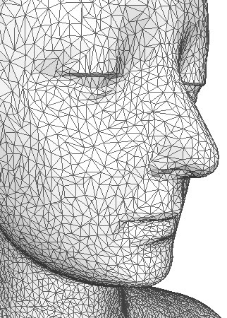
Most objects in computer games are stored as "Polygonal Meshes", which is a collection of polygons or "faces", that form the surface or "skin" of the object.
Benefits of using meshes
Problems with meshes


Meshes can be used to model both solid shapes and thin "skins". The object is solid if the faces fit together to completely enclose a space or a volume, this is called a closed surface. Most of the pictures of meshes on this page show objects made of white or grey triangles with black borders. This is done to show the structure of the mesh. When the object is drawn so that all the edges are visible and the object is transparent, this is called a wireframe. Later in the course we will learn how to colour and smooth the triangles when drawing so the object looks more realistic.

For a mesh model we specify a set of points in space and we connect various pairs of these points to form edges. A set of 3 or more points (vertices) will form a polygon. A number of polygons may form a surface. And a number of surfaces will form an object.
Polygon meshes can be used to approximate almost any kind of object, these meshes will have a number of properties which allow us to discuss and compare different meshes. The properties will also affect how a mesh can be rendered
A mesh represents a solid object if its faces enclose a positive and finite amount of space
A mesh is connected is there is an unbroken path along the edges between any two vertices. If a mesh is unconnected, it is usually considered to be two objects
A mesh is simple is there are no holes in it
A mesh is planar if every face is a planar polygon.
A mesh is convex if a line connecting any two points lies wholly inside the object.

Generally, graphics algorithms require that faces be planar (flat). A triangle between 3 points is guaranteed to be planer, other polygons (squares, quads, pentagons etc.) might not be flat. This is one of the reasons that graphics renderers will only draw triangles. If you want to draw other polygons they often must be broken(tessellated) into triangles. For example, OpenGL will allow you to draw quads and convex polygons, but internally these are rendered as a number of triangles. By limiting rendering to triangles, the drawing algorithms can be highly optimised.

Consider the mesh in the figure above, we have 8 vertices and 12 faces (polygons).
This kind of mesh is known as a polyhedron, which is a solid mesh (encloses a definite volume) and all the faces are planer and it is simple (no holes). Polyhedrons are typically the simplest types of meshed to process and render, so many graphics systems will restrict meshes to polyhedrons.
In a polyhedron, no edges can be shared by more than 2 faces.
The number of vertices (V), edges(E) and Faces (F) on a polyhedron are related as follows; This is only true if the polyhedron has no holes (e.g. this not work for a doughnut)
\[ 2=V-E+F \]this is known as Euler's formula.
On a close sd mesh, each polygon has two "sides". On side facing into the inside of the mesh (back face) and another side facing outward (frontface). A view can only see one side of a polygon at at time. If the mesh is closed, a viewer will never see a back face unless she is inside the object. Later on it will become necessary to figure out if we are looking at a front face or a backface. This is done by adopting a convention about how we list the vertices of a polygon. When listing the vertices for a polygon we imagine that we are looking at the frontface and list the vertices in counter clockwise order. We will use this information later to determine if we are looking at a backface or a frontface (see Backface Removal).
Another way to think about it; if walking on the outside of the mesh, around the polygon, the centre of the polygon will be on your left when CCW order.
To describe a polygon mesh, two distinct types of information are required;
A good mesh representation must primarily be space efficient. In addition, if the topology of the mesh is to change (e.g. in a 3D modeling package) where polygons have to be split and merged and removed and inserted, there must be efficient access to the following kinds of information;
| All vertices around vertex |
| All edges of a face |
| All vertices of a face |
| All faces around a vertex |
| All edges around a vertex |
| Both faces of an edge |
| Both vertices of an edge |
| Find face with given vertices |
There are 3 main polygon mesh representations in use.
How long is the list of vertices needed to represent a cube? List the vertices (in correct order) for the red face and for the green face. The mesh is represented by a list of vertex coordinates. Typically these vertices are grouped into threes. Each group representing a triangle. As discussed, the vertices are stored in counter clockwise order.
|  |
|||||||||||
| Explicit Vertex representation for a cube |
This representation is not space efficient, because a shared vertex, will be stored many times. In a Cube for instance, each vertex is shared by 4 faces and 4 edges. Also it is unclear from this representation, which faces are connected to which, this make manipulation difficult.
In the representation we have a vertex list, which contains the (x,y,z) coordinates of all the vertices in the mesh. Each vertex is only stored once. There is a also vertex index which lists the vertices for each face(each group of three represents on triangle). The vertex index does not contain the coordinates of each vertex, instead, it contains indices or pointers into the vertex list.
This representation is much more space efficient because, even though the vertex indices are repeated, they take up much less storage space than the 3 coordinates of a vertex.
|
|
 |
Assume an index takes one byte of storage. How much total space is required for the indexed representation of the cube? This representation is the most common representation used for rendering in computer games and graphics. However, it is still difficult to answer question like which vertices are on an edge or which faces are touching.
Where dynamic changes to mesh topology are required for applications such as mesh editing, a more flexible representation is needed. The winged edge mesh explicitly represents vertices, faces and edges of a mesh. The core structure is the Edge List which lists the faces, vertices and the 4 closest neighboring edges for each edge. There is also a vertex list which stores the vertex coordinates and a list of edges for each vertex. Finally there is a Face list which stores the edges belonging to each face
This representation is widely used in modeling programs to provide the greatest flexibility in dynamically changing the mesh geometry, because split and merge operations can be done quickly. Their primary drawback is large storage requirements and increased complexity due to maintaining many indices. See this article for more details.


An unstructured set of 3D point samples. Acquired from a range finder, laser, computer vision, 3D Scanner. Point clouds themselves are generally not directly usable in most 3D applications, and therefore are usually converted to triangle mesh models.


Range imaging is the name for a collection of techniques which are used to produce a 2D image showing the distance to points in a scene from a specific point, normally associated with some type of sensor device.

Most meshes consist of many connected triangles forming a smooth surface. One way to take advantage of this to use a triangle strip.

For example, the four triangles in the diagram, without using triangle strips, would have to be stored and interpreted as four separate triangles: ABC, CBD, CDE, and EDF. However, using a triangle strip, they can be stored simply as a sequence of vertices ABCDEF. This sequence would be decoded as a set of triangles ABC, BCD, CDE and DEF.
Note however, that triangle strips can only be used over a smooth mesh where vertex properties (colour, normal, etc) are shared between triangles. Triangle strips cannot be used where two of the triangles meet at a "seam", where the mesh surface changes abruptly. For example it would not be appropriate to render an entire cube as a triangle strip as each side of a cube would have different properties.

Can we draw the sides with one triangle strip? Another example would be the cylinder above. We could use 3 triangle strips to form the sides of the cylinder. We should not create a strip which contains triangles from the sides and the top as there is a seam and the vertices for the top will require different properties than the sides. The side and top do not form one smooth surface. The tops could be drawn using a triangle strip, but more appropriate would be a triangle fan.
© Ken Power 1996-2016